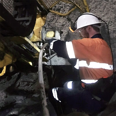
Grange Resources operates Savage River Mine which lies
100km Southwest of Burnie in Tasmania.
The magnetite ore body stretches 25km south of the
Savage River township ranging in thickness from 40m
to 150m. Current production is two million tonnes of
premium iron ore pellets; this is expected to rise to
nearly three million tonnes as the open cut mine extends
underground.
HMA Geotechnical was contracted to install vibrating
wire piezometers both in the open cut pit and the newly
opened underground drive.
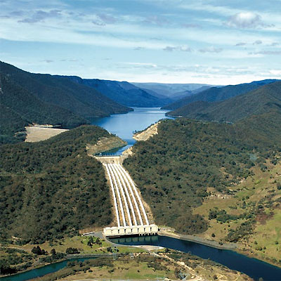
In line with Australia’s commitment to reduce carbon
emissions and move towards renewable energy, Snowy
2.0 is a major project estimated to cost in the region of
A$5.2 billion.
Early feasibility studies investigated the viability of a
tunnel linking Lake Talbingo and Lake Tantangara.
Situated underground, along the tunnel would be the
power station housing six turbines capable of generating
2000 megawatts. Power generation is not expected until
2025.
The initial site investigation by SMEC and GHD led to
HMA Geotechnical being awarded the instrumentation
installation work.
HMA Geotechnical began installation work in November
2017 and completed the work in February 2021
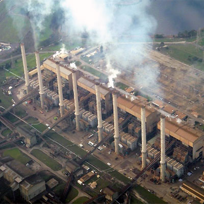
Located in the Latrobe Valley, Victoria, Australia.
Hazelwood Power station was constructed during the mid
to late 1960’s and supplied Victoria with up to 25% of its
power.
The brown coal fuel for the eight 200MW turbines was
mined from the adjoining pit.
In 2005 the World Wildlife Fund reported that Hazelwood
power station was one of the world’s most polluting,
emitting 3% of Australia’s annual greenhouse gas
emissions.
In 2016, Engie, the joint owner, announced the power
station and mine would close and in March 2017 it finally
closed.
The power station was demolished in November 2020.
The 1,281hectare mine presented another problem.
The plan is to allow the void to fill with
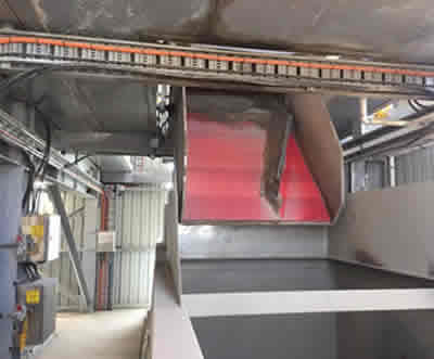
The sheet was cut to size and fitted as a lining on a diversion chute coming off of a conveyor carrying dry mix cement (cement powder and sand mixed with 10 to 14mm aggregate) in to a hopper. The conveyor feeds two hoppers with half the product going to each hopper.
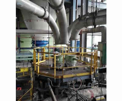
HMA Wear Solutions has completed a major US$1.5 million contract to manufacture 279 ceramic-lined pipes – including all fasteners, gaskets, and pipe supports – for an upgrade project at the Ombilin power station in remote Sawah Luto in West Sumatra, Indonesia. This ageing power station was experiencing major issues in terms of efficiency – especially in and around its pulverised fuel delivery system, resulting in increased emissions from incomplete combustion.
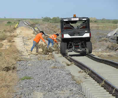
This purpose of this vehicle is primarily as a light weight personnel carrier that can be rapidly deployed on rail and used for rail inspection. With rail in good condition, it can get to the job site very quickly at 60km/hr.

Various processes onboard ships, such as machinery wash-down, maintenance, and leakage, generate oily wastewater. This contaminated water flow collects in the bilge of the ship. Marine diesel, lubricating oils, grease, as well as other contaminated water flow collects in the bilge of the ship.

A Califonia refinery produces xylene for use as a commercial product and a precursor for petrochemical manufacturing. A primary component to the products of xylene is the isolation and purification of the chemical from a complex mixture of petroleum hydrocarbons.

Hydroelectric dams produce electric power by harnessing the force of the water flowing through the dam. There are numerous sources for oil spillage: The hydroelectric turbines are lubricated by lubrication oils, The very large water control valves are normally hydraulic powered and are lubricated with various greases and oils, Vehicles including fork lifts, trucks, etc, can spill oils and fuels.

A paper plant in the Eastern United States uses 500 gallons per minute filtered pond water for cooling lubricating oil in its paper line. The resulting warmed water is diverted to an onsite pond.

A wastewater treatment company operated an oil/water separation facility on a multi-acre industrial site in Northern California. Its purpose was to recycle oil products for profit while at the same time providing a wastewater treatment service for industries based in Northern California.

A municipal power plant in the southern United States operates more than 10 stationary power plant engines capable of producing 52 megawatts of electric power. The plant is part of a larger statewide power grid system.

A plant located in the eastern United States manufactures phenolic resin for applications in plastics molding. This plant uses well water for cooling its reaction process and then discharges the water into a local creek.
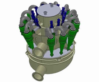
A cluster of four 380mm De-watering Cyclones were sent in to HMA for refurbishment. They were originally lined with 12mm alumina tiles.
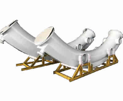
HMA Wear Solutions has collaborated with design engineering company Lycopodium on the ceramic piping specification for the Cobre Panama project by First Quantum Minerals Ltd. of Canada. This $6.3 billion copper project is anticipated to be one of the few new ‘red metal’ mines to enter production by the end of the decade.
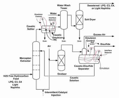
By contacting hydrocarbon with mercaptan rich caustic, a very stable emulsion may form in the UOP Merox process. This causes significant quantities of caustic to carry over with the product.
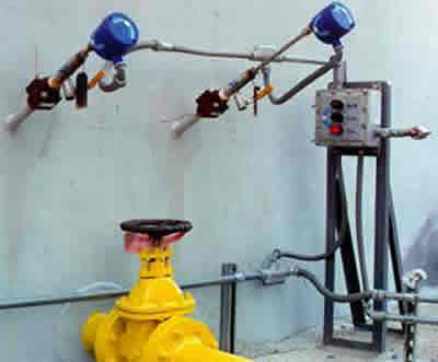
Storage tanks containing hydrocarbon feedstocks, intermediates and finished products will, over time, accumulate a water layer in the bottom of the tank (exceptions are water-soluble hydrocarbons such as alcohols and ethers). Standard industry practice is to periodically drain the water from storage tanks so that the water does not adversely impact specifications of the hydrocarbon.
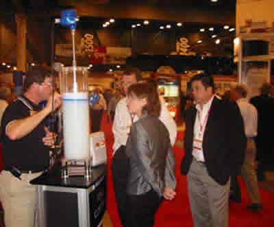
Common techniques for foam detection include: DP gauges, capacitance probes, guided wave radar, electromagnetic radiation, neutron-backscatter, sonic echo devices, flow meters, and sight glasses. Most of these do not offer early foam detection.
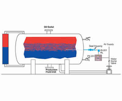
Produced oil contains water in highly variable amounts. Heater-treaters heat the produced fluid to break oil/water emulsions and to reduce the oil viscosity. The water is then typically removed by utilizing gravity to allow the free water to separate from the oil.
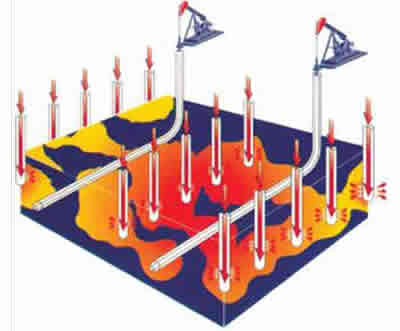
As oil becomes heavier and more viscous, it is more and more difficult to get the oil to flow into the well bore where it can be pumped to the surface. This heavy Canadian oil is often referred to as bitumen and has an API gravity ranging from 8—14.
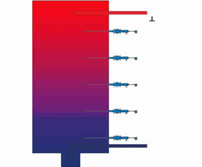
Many manufacturing processes produce hydrocarbon waste that contain varying amounts of water. Some of these industries are: Refining, Chemical Manufacturing, Steel, Metal Finishing, Pharmaceutical
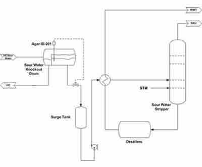
A common problem in the Sour Water (SW) Stripper Unit is caused when hydrocarbon is discharged with the sour water from the Knock-out Drum into the Surge Tank which feeds the SW Stripper Column (see simplified process flow diagram). The hydrocarbons will vaporize with the sour gas being sent to the Sulfur Recovery Unit (SRU).
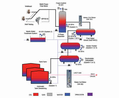
Refineries currently utilizing Agar systems increase throughput up to 20% and significantly reduce theamount of process upsets - resulting in up to an 80% reduction in hydrocarbon under carry to the waste water treatment plant as witnessed by the Environmental Protection Agency (EPA). Agar systems provide an unmatched ability to optimize difficult separation processes by utilizing concentration measurement and control.
The Agar System 2 provides automatic monitoring and indication of accumulated hydrocarbon in API skimmer systems. When used in conjunction with mechanical or pneumatic actuators, the system provides complete
automatic control of the oil recovery process.
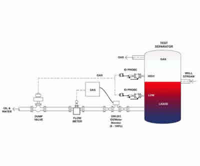
Determining the production rate from oil wells is simpler and less costly because of AGAR’s advanced technologies. For many years complex 3-phase separators were the industry standard because measurement technologies required the separation of the hydrocarbon, water, and gas phases.
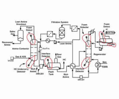
Contamination of amine systems (Refer to Figure 1 on following page) results in operational and environmental challenges for the operator. Contaminants include: Particles such as iron sulfide with the feed, Heat stable salts, Surface active agents, Liquid hydrocarbon in the gas feed, Carboxylic acids formed from oxygen entering the amine system, Corrosion inhibitors and water treatment chemicals entering with makeup water and wash water
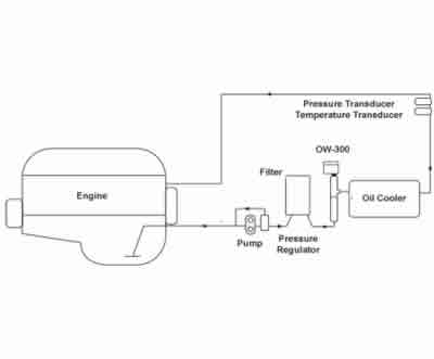
Industrial lubrication systems require close monitoring of the lubricating fluid to detect contaminants and prevent the resultant degradation of the fluid. Contaminants such as water and metallic fines are commonly monitored manually, requiring routine sampling and laboratory analysis.
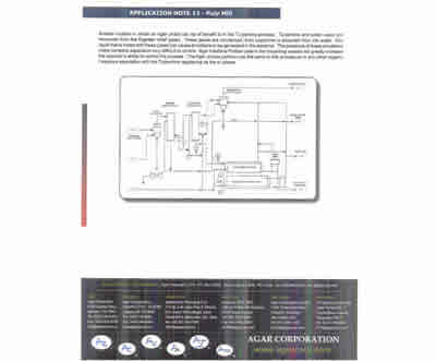
The manufacturing of Paper using the Kraft Mill process generates liquids called Black Liquor and Soap in the digester. When the wood is cooked in the digester a caustic bath is used.
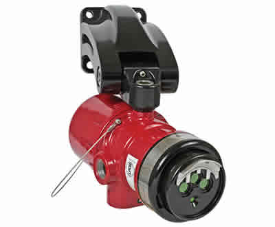
By itself, hydrogen is colorless, odorless, tasteless and nontoxic. But when even small amounts of this seemingly harmless substance mix with air, it morphs into a major fire hazard.

In 2012 a large refinery in New South Wales came to a realisation – it needed to convert to a fuel tank farm and subsequently reduce staffing levels. Such a significant change would inevitably lead to the challenge of upgrading its fire protection and detection systems, to allow the site to become more automated and responsive in emergency situations.
